A cartridge hand pump is a compact hydraulic power component. Unlike common large independent hand pumps equipped with oil tanks, this unit is designed as an integrated component similar to a cartridge valve. It is installed by screwing it directly into a hydraulic manifold via threads.
Core Features
-
Cartridge Design: The pump body features standard threads, such as the common SAE 10-2 or 16-3 cavities. It can be installed directly inside a manifold block to significantly save system space.
-
Compact and Portable: These units are generally very small in volume. The handles are often designed to be detachable or capable of 360 degree rotation to facilitate operation in confined spaces.
-
Integrated Check Valves: Most cartridge hand pumps have suction and discharge check valves integrated internally. You simply screw the unit into the valve cavity to begin operation without requiring additional wiring or external valve components.
Main Applications
These pumps typically serve as auxiliary or emergency equipment:
-
Emergency Backup Power: Provides manual drive for hydraulic actuators, such as retracting cylinders or releasing brakes, when the main pump fails or power is lost.
-
System Pressure Compensation: Used for micro oil replenishment in systems requiring long term pressure maintenance.
-
Pressure Testing: Acts as a pressure source for small, portable testing devices.
-
Heavy Equipment Parking Brake Release: Manually releases parking brakes on construction machinery that cannot start, allowing the equipment to be towed.
Cartridge Hand Pump HP-10
Cartridge Hand Pump is indispensable in some hydraulic integrated circuit. Cartridge Hydraulic Hand Pump could be mounted inline using standard housing or special blocks. Handle is offered as option in case of frequent operation.
Cartridge Hand Pumps HP-10 OPERATION

When the operator is pushed, the valve delivers a nominal flow of 10.0cc to the port. When the operator is pulled, the valve suctions fluid from the port.
Cartridge Hand Pumps HP-10 Cavity

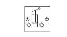
Cartridge Style Hand Pump HP-10 Symbol

Cartridge Style Hand Pump HP-10 SPECIFICATIONS
Operating Pressure :288Bar
Flow : 10.0 cc per stroke.
Internal Leakage :2 drops/min. max. at 138Bar
Temperature:-22°F to +250°F (-30°C to +120°C)
Recommended Filtration :ISO 16/12
Fluids:Mineral-based fluids. For other fluid compatibility, consult factory.
Body Material :Anodized 6061T6 aluminum
Cartridge Hydraulic Hand Pump HP-10 INSTALLATION DIMENSIONS

Operated Cartridge Hand Pump HP-08
The Operated Cartridge Hand Pump screw into an industry standard cavity machined into the manifold. Installation takes seconds rather than piping up, the unit is very compact and highly cost effective. Inlet and outlet non return valves are integrated into the unit. A 360 degree swivel allows operation to suit the operator.
Operated Cartridge Hand Pump HP-08 FEATURES

Cast Beam for heavy duty applications.
Hardened parts for long life.
Industry common cavity.
Operated Cartridge Hand Pumps HP-08 OPERATION
When the operator is pushed, the valve delivers a nominal flow of 8.8cc to the port. When the operator is pulled, the valve suctions fluid from the port.
Operated Cartridge Hand Pumps Cavity

Cartridge Hydraulic Hand Pumps HP-08 Symbol
Cartridge Hydraulic Hand Pumps HP-08 SPECIFICATIONS
Operating Pressure :288Bar
Flow : 8.8 cc per stroke.
Internal Leakage :2 drops/min. max. at 138Bar
Temperature:-22°F to +250°F (-30°C to +120°C)
Recommended Filtration :ISO 16/12
Fluids:Mineral-based fluids. For other fluid compatibility, consult factory.
Frequently Asked Questions
Your Hydraulic Solutions, One Step Away
Whether you need a standard product or a custom solution, our team is here to deliver precision-engineered hydraulic systems tailored to your needs. Let’s bring your project to life with the right hydraulic solutions.
Contact Us
Interested in our products, pricing, MOQ, or customized solutions? Fill out the form below to submit your inquiry or request a quote, and our team will get back to you within 24 hours.
Latest News
The company’s business philosophy is to create a quality brand and win customer loyalty, not only by providing customers with quality products but also by offering excellent after-sales service.