
Logic valves hydraulic work by using pilot pressure, spring force, and pressure acting on different valve areas to open or close a flow path inside a hydraulic manifold. In simple terms, the valve works like a hydraulic switch: when the required pressure condition is reached, it opens, closes, blocks flow, or allows oil to pass.
What Is a Hydraulic Logic Valve?

A hydraulic logic valve, also called a cartridge valve or 2-way directional valve, is a compact insertable component used to control high-flow fluid direction, pressure, or flow rate inside a hydraulic manifold. It can work as a directional valve, pressure valve, check valve, or flow control valve depending on the pilot circuit and valve design.
How Does a Hydraulic Logic Valve Work?
The diagram below gives a simple overview of how a hydraulic logic valve works. Read it from left to right: it first shows how pressure area affects valve movement, then how pilot pressure opens or closes the valve, and finally how the same valve principle can be used for pressure control, check valve function, and flow control.
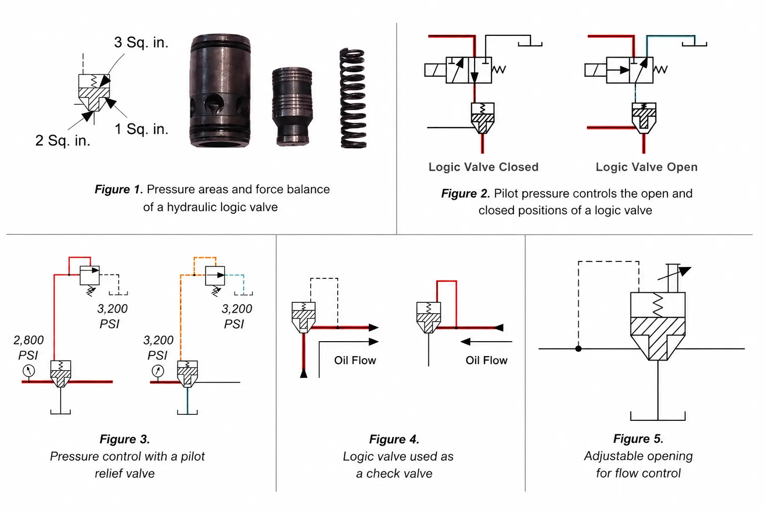
1. Pressure Area Decides Movement
A hydraulic logic valve opens or closes according to pressure acting on different valve areas. The basic rule is:
Force = Pressure × Area
When the pilot area is larger, the same pressure can create more force and keep the valve closed. This is the basic reason why logic valves hydraulic respond to pressure signals instead of working only as simple mechanical valves.
2. Pilot Pressure Controls Opening and Closing
In a pilot-to-close logic valve, pilot pressure keeps the valve closed. When pilot pressure is released, inlet pressure can open the valve after overcoming the spring force.
The spring mainly keeps the valve seated when there is no system pressure. During operation, a small pilot valve can control a much larger hydraulic flow inside the manifold.
3. One Valve Can Support Different Functions
Logic valves are versatile because the same basic valve element can work in different ways depending on the pilot circuit and mechanical adjustment.
A logic valve can be used for:
This is why a logic cartridge valve is often used in compact manifold systems where one valve principle needs to support different hydraulic functions.
For custom manifold projects or replacement evaluation, contact Jade Crown for hydraulic logic valve support with your valve model, drawing, pressure, flow, and cavity details.
Common Types of Hydraulic Logic Gates

Hydraulic logic circuits can use different valve configurations to imitate basic logic functions. These designs help the circuit decide when flow should pass, stop, or switch according to hydraulic pressure signals.
- 1
An AND gate requires two or more independent pilot signals to be present at the same time before the circuit triggers an action or allows flow. If one signal is missing, the valve will not complete the required function.
- 2An OR gate is often created with a shuttle valve. It directs fluid from the higher-pressure inlet to one outlet, allowing either of two hydraulic sources to operate the same function.
- 3
A NOT gate uses an inverted control logic. A normally open valve closes when a pilot signal is applied, so the hydraulic output is opposite to the input command.
These functions help logic valves hydraulic build more complex hydraulic control circuits without relying only on large directional valves.
Can Jade Crown Support Replacement Evaluation?

Jade Crown can support replacement discussions for hydraulic cartridge valve projects, including requests related to a logic cartridge valve rexroth reference. Before confirming a possible equivalent option, the valve must be checked according to real system conditions, not appearance alone.
For a faster evaluation, you can send us:
With these details, you can contact Jade Crown with your valve model or drawing for replacement evaluation.

